Daley Train Log
Page 2
I am beginning today on an optimistic note. I have had a look at my track layout and have confirmed my understanding that the layout consists of a mainline plus one reversing loop.
I will need to remove the wiring that I presently have for the reversing loop and install an MRC "reversing loop module" which is simply a very small black module containing some circuitry that will ensure that the current is automatically adjusted when a train enters and leaves this section. All that is required is that I attach to two wires from the module to the track in the reversing loop and two wires to the mainline track.
The MRC Prodigy Command Station (aka base station) is connected to the mainline track with two wires. Another two wires connect to the Program Track which is a small section of track, isolated from the mainline track, where I can place locomotives and program them for running on the mainline. I now need to add two insulators to isolate a small section of track in my Coaldale classification yard.
What I am just beginning to realize is that the large control panel that I once thought I would have to build is no longer necessary. In the short term I can control all of the turnouts manually. In the longer term I can add decoders to some of the mainline turnouts and then control those with my wireless cab. This is beginning to look like the entire operation is dramatically easier with DCC.
To summarize, I need to:
1. Remove the wiring for the reversing loop. Done.
2. Attach the reversing loop module to the reversing loop track and to the mainline track.
3. Insulate a small section of track (now called the Program track) in the Coaldale classification yard. Done.
4. Attach the Command station to the mainline track and to the Program track. Done.
5. Connect the Command station to a power supply. Note: the command station takes DC 15 volts/ 3.5 amps as input (from the MRC switch power supply) and outputs a DCC signal with 14.5 volts amplitude. Done.
6. Plug the AC line cord from the power supply into a wall outlet. Note: the MRC switch power supply takes AC 100 - 240 volts 50/60Hz as input and outputs DC 15 volts/ 3.5 amps. Done.
6. Verify that the handheld cab is adequately charged (i.e. greater than 4 volts). Done. It is presently 4.2 volts. The handheld cab now sends and receives signals between itself and the Command station. The Command station sends DCC signals to the track. The decoders (either mobile - locomotives, or stationary - turnouts and accessories) pick up the signal and run the appropriate equipment.
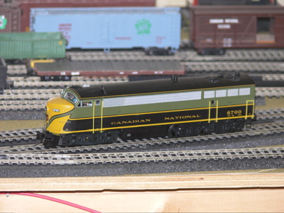
7. Place a decoder equipped locomotive (CN 6700 C-liner diesel) on the Program track. Done.
8. Turn the cab on. Done.
The next step is to learn how to communicate with the locomotive.
However before I begun the above steps, I will need to buy some more connector sections of track (2 for the reversing loop and 1 for the Program Track. Nonetheless I now think that I understand what I am trying ro do. A very good start. 11:00 am
4:00 PM
I have completed all of the modifications to the wiring for the layout - with the exception of adding the reversing loop module. I want to carefully review all of my steps and make sure that I have everything ready before I try to turn the power on.
5:00 PM
My first attempt at using DCC has met with mixed results. I have been able to move the locomotive and have both sound and lights. But this is all on the Main Track. I do not appear to be communicating with the locomotive on the Program Track.
There appears to be power on the Mainline Track (but not on the Program Track) as soon as the power unit is plugged in. Turning on the Handheld Cab is only used to send communication signals to various decoders. At the moment I only have one locomotive with a decoder installed. Therefore I want to end each session with the locomotive at a speed of zero. Ideally, I actually want it with no power until I tell it something positive. At the moment I am not sure how to do this.
8:00 PM
I have played with the settings a bit more. I think part of the problem may be my understanding of what should be happening at certain times. I now think that when I place a locomotive on the Program Track, all that happens is that the decoder is programmed. I then must physically remove the locomotive from the Program track and place it on the Mainline Track.
At the moment I also need to remove the power on the layout in order to do this, as the locomotive wants to engage as soon as it touches the Mainline Track.
8:30 PM
Substantial progress! I am finally beginning to get the feel of what I am doing. The Handheld Cab contains a number of function keys (particularly 1 - 9) that control various actions. For example pressing F1 starts the bell clanging and F2 blows the horn. F6 is the key start-up command. F9 is shut down. Thus F9 is what I want to leave the locomotive in when I turn the power off. I am now beginning to have the locomotive have the appropriate sounds as I begin moving through the yard. I have never been able to do this when I controlled the trains using regular analog DC.