Daley Train Log
Page 39
I am hoping to attach the Digiterax D64 this morning and then wire four turnouts (601, 603, 604 & 613) to the DS64. I am aiming to have these four turnouts operational and controlled by the MRC Cab before the end of the day. This will also involve drilling holes near the turnouts for the wires. Since I will be making a bit of a mess doing this I also plan to cut a small section off the table top in the Jasper District to give me a little more room in the aisle between Jasper and Lone Pine.
It took me almost 3 hours to wire the four turnouts and attach the wires to the D64.
Drilling the four holes for turnouts 601, 603, 604 & 613 only took a few minutes. Then the fun began.
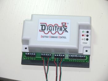
The Atlas turnouts come with a piece of 5-color wire (Red, Black, Green, Yellow, Blue). The turnouts only use 3 wires. Looking at the D64 I noticed that the labels for the output signals are labelled R1, G1, P+; R2, G2, P+; R3, G3, P+ and R4, G4, P+. Therefore I decided to separate off the Yellow and Blue strands and discard them (i.e. put them in a box for possible use at a later time). I then planned to attach the red wire to R1, the Green wire to G1 and the Black wire to P+ and repeat the process for the next 3 turnouts. That keeps everything consistent and reduces the chance of confusion later. (I am confused enough at the moment!).
I then decided to remove the turnouts from the layout and attach the wires to each turnout while sitting at my work table. This was much easier than trying to attach the wires while the turnouts are on the layout as these four turnouts are the most difficult to reach of all my turnouts. Then I returned the turnouts to the layout and passed the wires through the holes I had drilled. So far so good.
The next step was to decide where to locate the D64 under the table and then cut the wires to an appropriate length. Once again, everything proceeded as planned. I mounted the D64 to the underside frame and was ready to hook-up the wires to the D64. Still good.
The remaining step was to attach the wires to the D64. This turned out to be very tricky. The wires are small, the holes that the wires fit into are small, and after about 20 minutes of trying to get the first set of 3 wires attached, I realize this was not going to work.
Clearly, now, this should have been the first step. Thus I disconnected all of the wires from the turnouts, and took them plus the D64 to the work table where I fitted the wires into the module. Good.
Then I reattached the D64 to the underside frame. Good.
Then I pushed the wires up the appropriate holes and reattached them to the turnouts. This was still difficult, but manageable. Good.
The last step in the physical set up was to attach 2 wires to the D64 called Track A and track B. This will be the source of power for the D64. At first I thought I would have to actually connect the 2 wires to the tracks but I then realized that I could connect then to a connector panel that has wires going to the two tracks. Much easier. Good.
I then sat back, had a coffee, and reread the manuals (both the Digitrax D64 manual as well as the MRC Prodigy Wireless manual). The main trick is the same as with any computer manual - figuring out what is important and what does not apply to the present situation. The Digitrax manual is 19 pages and only 2 pages describe how to connect the wires and 1 page describes how to program the D64. The MRC Prodigy manual is 23 pages and only page describes how to use the handheld Cab to control turnouts.
I then sat down under that layout table and pushed the ID button on the D64. I then began following a short sequence of steps with the MRC handheld Cab. I repeated this 4 times, once for each turnout. Done. Only one question remains. Does it work? Time for a coffee. If it doesn't work I am not sure what I will do next...
I turned on the power to the layout and turned on the handheld Cab. I typed in the number 604 and pressed 1 for "on". Nothing. I then tried typing in 601 and 2 for "off'. Nothing. This was not looking promising. Then I tried typing 604 and press 2 for "off". There was a sharp click as the turnout changed status! It works! The initial two tries just happened to pick values that reflected the current situation and so nothing happened.
Needless to say, I was ecstatic. It really wasn't that difficult, but one wrong or loose wire and I would have been in deep difficulty trying to troubleshoot it.
I now have four mainline turnouts under DCC control, all in the Jasper District. The eventual goal is to have all of my mainlne turnouts under DCC control. I have one more D64 module to install. Then I will have to think about buying more. But the main hurdle had been overcome - I now know how to install and operate these modules.
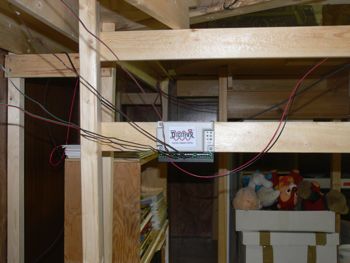
Here are a few photos of the DS64:
 |
 |
DS64 under table |
DS64 |
 |
|
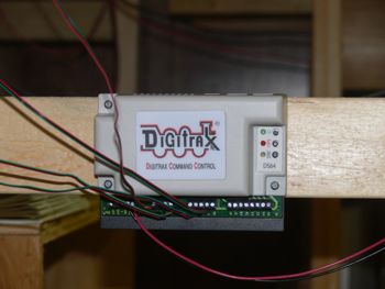
DS64 - ID button is the top one with the green LED |
pulling wires up from DS64 |
I have finished trimming a part of the table top in the Jasper District. This gives me a little more room between Jasper and Lone Pine and makes it a little easier to walk around the layout.
I have accomplished all that I had hoped for today. This does not always happen.