
Daley Train Log
Page 32
My goal this morning was to install my first manual Caboose Industries Ground Throw. This turned out to be relatively straight forward, a bit to my surprise.
Here is a list of the steps that I took:
1. Remove surface mounted Atlas switch machine.
2. Cut styrene (0.040" thick) base to size 13/16" x 1".
3. Cut notch in styrene base for wire link.
4. The base should be painted grey to simulate cement.
5. Cut throw bar on turnout so none of it sticks beyond the ties.
6. Cut small piece of foam track bed to place under the styrene base.
7. Glue foam to styrene base.
8. Cut piece of piano wire 1 1/8" long.
9. Bend piano wire 90 degrees 1/8" from each end. One end of wire will fit in hole on turnout throw bar. The other end will fit on the Ground Throw throw bar.
10. Cut off one end of Caboose Ground Throw throw bar.
11. Drill 2 holes (#55, 0.052mm drill bit) in styrene base to attach Caboose Ground Throw to styrene base.
12. Use Hob-Bits (0-80 1/4 #H806) to attach Caboose Ground Throw to base.
13. Attach piano wire to turnout and Caboose throw bar.
14. Nail styrene base to table.
I expect that I will need approximately 30 such Ground Throws, but these can be added on an intermittent basis. The styrene bases and piano wire links can be mass produced.
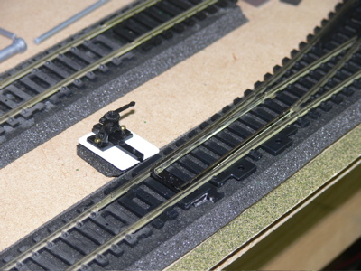
This turnout identification number is 451 (4 = Black Diamond District, 5 = spur line, 1 = sequence number). This is the first manual turnout for my layout.