 |
5:30 PM I cut some wooden strips that could form the berms around my two oil tanks. I cut them to a scale that fit a walkway that is supposed to go over them but when I put them on the layout they overwhelmed the space available. I am now debating trying a smaller and thinner size for the berms as well as giving serious thought to simply not having them. This is one of the features of any modeling activity (including computer models), namely what to include and what to exclude.
I finally have gotten around to beginning to wire the Lower Mainline loop. I attached a 4-position dual row barrier strip to the table frame near the terminal track close to where the control panel will be located. I used 14 gauge red and black wire to connect the barrier strip to the power source, then used 20 gauge red and black wire to connect the barrier strip to the terminal track. At that point, in principle, I should have a working Lower Mainline loop.
Success. I had no difficulty running my locomotive and 3 cars around the loop. The next step will be to run 14 gauge red and black wire from the barrier strip to another about a quarter of the way around the loop which will also have a connection to a section of terminal track. I am planning to have a total of 4 such connections around the loop. This is a small step, but it is the first step in what will eventually be a fairly sophisticated DCC wired layout. At least now I know that my basic understanding of barrier strips and layout wiring is sound. It is a good feeling.
I have also decided to keep my turnout controls above the table. This is much simpler than trying to remount them under the table. My priority is to have a working layout. Once that is accomplished, hopefully by Christmas, then I will think about making small changes as I see fit.
10:00 PM I have spent the last hour making minor adjustments to the track layout for the Lower Mainline Reversing loop. My earlier idea of having 3 terminal tracks fell apart when I noticed that there was no area near the control panel that would allow a section of teminal track. All of the track pieces were either turnouts, curved sections or short straight sections. By the time I had found an area that would accommodate a regular length straight section (i.e. a terminal track piece) I was too far away from the control panel to run a short wire (i.e. less than 3') to the barrier strip.
I now have changed my plan to only using 2 terminal tracks and have made the necessary changes to the track layout to be able to exchange two regular length straight sections with 2 terminal track sections. Now I need to buy the 2 terminal track sections.
12:00 PM I am on day 2 of my electrician's apprenticeship. I have added a second barrier strip to the layout and have verified that my approach is still sound and not creating a short circuit. This took me about an hour. It takes time to to make sure that the wires are all cut to the proper length, to strip the ends of each piece of wire and to attach the wire to the terminal strip. I remember reading somewhere that one could use spade connectors instead of having to wrap the wire around the barrier screws. I would like to try this and see what I think of it in terms of ease and speed of installation.
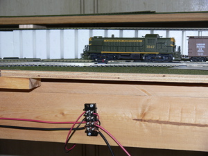
Here is a photo of the first barrier strip that I installed yesterday with the additional wires leading out of it on the left that go to the second barrier strip.
The top two wires on the left attach to the terminal track section under the locomotive. The two bottom wires on the right go to the power source. I now have two barrier strips attached and have two more to go to complete the wiring for power for the Lower Mainline loop. This wiring will also work for when I convert over to DCC in a couple of months.
I added one additional turnout to the loop which will mean a revision to my diagram for the control panel. There is always some little adjustment that (hopefully) improves things a little.
6:50 PM I have modified my layout diagram (with a pencil) to indicate the location of each turnout, the location of the terminal strips, the control panels, and I have given names to the two switching yards. The refinery complex will be called Distillery Row and the town will be called Happy Valley.
I have added the remaining two barrier strips and have now completed wiring the Lower Mainline loop. It consists of 4 terminal tracks which connect to the power source. I have run my test train on this track and it works fine. This represents the complete wiring of the first Power District. There will be four such power districts on the lower level, two for the mainline and one each for the two switching areas.
The next step is to wire the Lower Mainline Reversing loop. This will require 3 barrier strips to provide power to 3 terminal tracks equally spaced around this section of track. Reviewing my layout diagram, I see that it may make sense to replace 2 of the mounted 4-position barrier strips with 6-position barrier strips and to then have one connection to the Lower Mainline loop and another to the Lower Mainline Reversing loop. If I had been thinking this through at the outset I could have set this up initially and saved myself a lot of work. However my goal at the time was to make sure I had the initial wiring under control, which I now have. Once I have this reversing loop wired, I will make a preliminary check that my switching yards will all fit as I planned and then I will redo the mainline track, mounting it permanently on a road bed and even adding the rock ballast to make it look realistic.
I then redid wooden berms for the two oil tanks by reducing their size by about half. They now look much better and I will be able to begin working on the refinery diorama.
5:40 PM I am making progress on a number of fronts. I mounted the small piece of plywood to provide a grounding for the Lower Mainline Reversing loop track where it cut across an open corner between two sheets of plywood. Done. Then I decided to build the supports for the Lower Mainline Control Panel. I made this from some scrap material left when we had our hardwood floors installed a few years ago. I then cut a rectangular piece of plywood from some scrap 1/2" plywood. Then I mounted 13 Atlas switches for the 13 turnouts on the Lower Mainline loops. I have now painted the board black. Tomorrow I hope to give it a second coat, and then it will be reading for placing on the layout. Wiring the switches to the turnouts may take a few days, but I don't anticipate any difficulties.
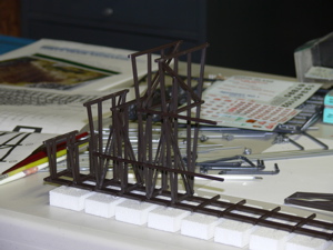
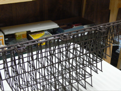
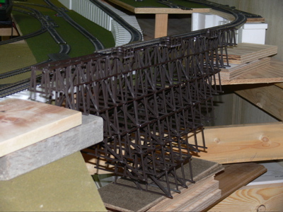
I have also been working on the wooden trestle kit. The main remaining task is to assemble the various sub-assemblies. Here is a photo taken that shows that I am almost 1/3 of the way complete (it is upside down - the track is at the bottom in the photo).
I took a break in the early afternoon and visited the Model Baron hobby shop where I bought 2 pieces of terminal track, which I will need when I work on the Lower Mainline Reversing loop. I also bought some scenery materials for the oil refinery diorama. Although I am working on both the diorama and the trestle kit, these are not critical to the actual operation of the layout. Thus my first priority is to work on the wiring for the power and then to get all of the 13 turnouts on the Lower Mainline working. Then I need thumb tack down the track in the Happy Valley yard. This is where the majority of my switching will occur. Once I have the refinery diorama finished it will only take a couple of hours to thumb tack down the track in this switching yard. That will complete the Lower Mainline. I then need to relay the Lower Mainline track on a foam roadbed and add ballast to make it look realistic. At that point I will have a completely operational Lower level and will be ready to convert the layout to DCC. Once that is working, I will then begin to repeat the entire process for the Upper Level.
I read that the scale speed for HO layouts should be:
switching moves yard movement mainline mainline modern mainline I need to create a table that correlates these values with those on the power source.
9:00 PM It took less than an hour to thumb tack down the Lower Mainline Reversing loop. Thus I now have the complete lower level mainline track in place. The next step will be wire the reversing loop for DC (Direct Current) operation. This will allow me to run trains on it. When I purchase a DCC (Digital Command Control) system I will have to make a few changes to the wiring, but this should be relatively minor.
7:30 am Yesterday was largely devoted to working on the layout. Today will be more of the same. It is exciting to focus on this for much of the day as I can see substantial progress in the overall project. I am presently in the middle of 5 tasks:
- building a wooden trestle
- making an oil refinery diorama
- building a Lower Mainline Control Panel
- redraw schematic diagram for Lower Mainline
- wiring the Lower Mainline Reversing Loop
The wooden trestle kit is progressing nicely. I might be able to finish it today. I expect to begin glueing the berms for the tanks and then I will begin placing of the piping to join the tanks to the refinery and the oil platform. This may take awhile as I am not sure what is involved in this. The problem is not the actual placing of the pipes, but deciding where they should be placed. I will give the Lower Mainline Control Panel a second coat of black paint which should make it ready for using tomorrow. I also need to create a new diagram of the Lower Mainline showing the location of the turnouts and power connections. But the most important task will be to complete the wiring for the Lower Mainline Reversing Loop. There are only 2 pieces of terminal track on this section, but I think I will have to replace two of the barrier strips from my earlier wiring from a 4-terminal strip to a 6-terminal strip. However I am still not totally sure that I have the plan for wiring this section clear in my mind at the moment.
Looking at the above bullet list, I wonder if it would make sense to try to create a critical path chart of my activities. I could review my activities since I returned from Australia and easily build the chart that corresponds to what I have done so far. Then I could try mapping out what remains. I have a software program on my PC that can be used for this but I will have to find it and see if I can install it on my MacBook Pro.
1:00 PM I added a second coat of black paint to my Lower Mainline Control Panel. I then took a close look at my plans to wire the second Power Block (for the Lower Mainline Reversing loop) and realized that I want a totally separate circuit that will eventually connect to a circuit breaker module for DCC. This is best handled when wiring for DC by using an 8-position barrier strip with each of my 4 Power Blocks connected to two of the positions on the barrier strip. I had to visit an electrical shop for this, but now have it installed on the layout. I also bought a small package of "spade tongues" to see how they work. Great. I am now in the process of finding a location that sells these in packages of a specific size ( I will want about 40 that are suitable for 14 gauge wire).
7:30 am Yesterday I learned about using spade tongue connectors with my 14 gauge wire and was delighted with the result. I plan to return to the stores this morning and buy a package suitable for 20 gauge wire. It is much easier to connect the wire to the barrier strips using the spade tongues as one simply slides the tongue under the screw and tighten it whereas with just the wire one must wrap the wire around the screw which is a little more difficult with the barriers getting in the way. This will mean rewiring all of the connections on the Lower Mainline loop but I think it will be worth it.
Another reason for using the spade connectors is the ease of making modifications to the wiring. I now have a clear idea of how to wire the Lower Mainline Reversing loop for DC as well as for DCC. This will involve inserting an "Atlas Twin" connector module for DC and then removing that and adding a DCC reversing module when I convert over to DCC. I am beginning to feel that I am in control of the wiring now, and can pretty much do what I want. The combination of barrier strips and spade connectors makes the entire operation solderless and effortless: cut, strip, crimp and attach.
Although I have to redo some of my connections this morning, I am optimistic that I will have the entire Lower Mainline operational by late this afternoon. with the reversing loop working as well. My Lower Mainline Control Panel is complete and on the layout although I still need to attach a schematic diagram to it. That leaves the oil refinery diorama and the wooden trestle to work on.
I am thinking that I should scan a couple of the wiring diagrams from the magazines I am using that illustrate the nature of the circuits that I am building.
I now need to get on top of a couple of software packages, one for drawing (Mac) and one for critical path (windows).
I happened to read an article on realistic model train operation a couple of days ago that gave some guidelines - one of which was not to have any "duck unders". My layout has two of these! The argument was not so much the actual effort of getting down on your hands and knees and crawling under the benchwork to get to another part of the layout (which is what I thought was the reason, and which I didn't feel was that big of a problem) but the fact that such crawling makes it difficult to follow the train as you are controlling it under DCC (which I will be using shortly). This will be a weakness with my design. However I am going to go ahead and get this layout operational and see how bad the problem is before thinking about making any changes. I have read many articles over the years that talk about people who are always trying to make the perfect layout and never actually get one operational. I am determined to not be one of those people. My goal for today is to have the complete Lower Mainline operational (except for the turnouts).
The store will not be open for awhile yet so I think I will go down in the basement and glue the berms to my oil refinery diorama. Done. The next step will be to cover the berms with a soil groundcover. This will be a new activity for me as I have yet to learn how to do scenery. There is so much to learn. This is a great hobby.
2:20 PM I continue to underestimate the time it takes for me to accomplish a task. I have been working on the wiring for almost 4 hours and have only managed to accomplish a little. I have the Lower Mainline Reversing loop powered but I have yet to power the second terminal track. I lost over an hour when I first connected the power and nothing happened. I checked and rechecked my circuit and I could not understand why there was no power to the locomotive. Then, by nothing more than good luck I happened to move the power source just a small amount and suddenly there was power to the locomotive. A quick check revealed that there was one strand of wire that was touching an adjacent terminal on the power source and this was shorting out the current. I doubt if I would have ever seen it. This is the real world of electricity. It is very easy to have something minor bring everything to a halt.
I now have current in both the Lower Mainline loop as well as the Lower Mainline Reversing loop. That completes the power for the Lower Mainline but I still need to add one more source of power on the reversing loop to ensure that the signal remains strong over its entire length. I also wired my first turnout (turnout #2 on my schematic diagram) to the Lower Mainline Control Panel.
My spade connectors turned out to be more complicated that I imagined. It turns out that they work fine on the barrier strips but are too wide for use on the Atlas electric modules such as the switches that control the turnouts as well as the "Twin" connector that allows me to reverse the polarity on the tracks to avoid a short circuit with the reversing loop. I might have another look at these. Maybe I can file the edges of the spade so that they will work.
Midnight: I have spent the entire evening downloading the lastest version of AdeptTracker (for Windows) and then creating a file for my entire model train project. I used Parallels to click between windows and OS X and after about 5 hours had created an up to date project management file that shows what I have done to date and provides a preliminary indication of what remains to be done. I still need to add items for the future activities but I am pleased with the progress I have made. I will try to provide some screen captures of some of the displays tomorrow.
7:00 am Much of the day will be devoted to working on the model train layout. I was surprised and disappointed yesterday to notice that the spade connectors for the 20 gauge wire were slightly too wide for the Atlas modules, particularly the switch modules. I think I will take in one of these modules and see if the electrical store has anything that will fit it. It is possible to file my existing spades down but it would be nice if I had some ready-made connectors as there will be a large number of such connections on the layout.
I also want to reinforce the decision to use power to control the mainline turnouts, but will use manual throws for all the turnouts in the yards and sidings. One consequence of this decision in that I will only need 2 control panels, one for the Lower Mainline and one for the Upper Mainline. A further implication is that I can use the turnouts in their regular form in the yards and sidings and then slowly convert them to a realistic manual throw as I buy the necessary attachments. This all means that I am now ready to begin setting up the yard track for thumb tack attachment, which further means that I should soon have the entire lower level operational.
Once I have the Happy Valley track installed I will shift a major focus to rolling stock as I test the layout for operational ease of use by running trains and cars. Thus I will be able to mix development of the layout with actual use of the layout. This is happening much quicker than I suspected. I will then need to re-examine each locomotive and car to see that the wheels conform to NRMA standard, that the Kadee couplers work properly and are at exactly the right height, that the car has the correct weight (I need to find information on this.).
Setting up the yard track for Distillery Row depends on first finalizing the oil refinery diorama.
8:15 am I have begun adding predecessor information to my AdeptTracker project management file. I still have some work to do on this, but it is neat to see how the various components fit together. I expect that I will notice a few items that I may have forgotten, or which may have prerequisites that I have overlooked.
11:20 I returned to the electrical shop and was able to buy some narrow spade connectors that will fit the Atlas modules. Great! I am now set to continue wiring the Lower Mainline loop and Lower Mainline Reversing loop.
Even without working on the wiring, I am in a position to set down the track for the Happy Valley yard. Once this is in place I can thumb tack it down, add a couple of terminal tracks and wire them, and I will then be in a position to have a fairly complex set of switching activities.
I am now in a position where I can begin to review each of my rolling stock to verify that they meet all NRMA standards (wheel spacing, Kadee coupler height, car weight). As each locomotive and car is reviewed I want to make an entry in a data base to that effect as well.
Here is a web site that gives the NRMA standard for weight of a car: http://www.simplytrains.com/pages/hints&tips/track/betterrun.htm Basically it says that a car should weigh 1 oz plus 1/2 for each inch of length.
12:30 PM I have laid out all of the yard track for Happy Valley. The citizens should be happy as trains may soon be able to deliver supplies to the town which has only had a train station operational until now.
8:00 am Now that I have the spade connectors I want to redo all of the wiring that I have done so far to incorporate these wherever they are applicable. I also want to add a barrier strip and connect it to a terminal track on the Lower Mainline Reversing loop. Ideally I might thumb tack down the Happy Valley track and add a couple of terminal tracks and barrier strips to this part of the layout as well. The general goal is to have everything on the lower level operational with the exception of Distillery Row.
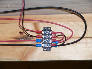
2:30 PM Considerable progress today. All of the wiring had been converted over to spade connectors. Here is a photo of one of the barrier strips:
The track for Happy Valley has been thumb tacked down and wiring for power has been attached. I now have an operational lower level layout consisting of a Lower Mainline loop, a Lower Mainline Reversing loop, and a Happy Valley switching yard. Both I, and the citizens of Happy Valley, are delighted as we now have a working train system that can be used to operate trains (using DC) while I continue to work on Distillery Row. Then I can turn my attention to the upper level where there is considerable work to be done.
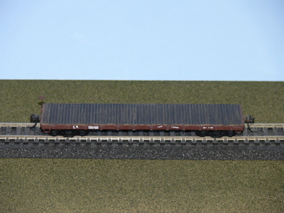
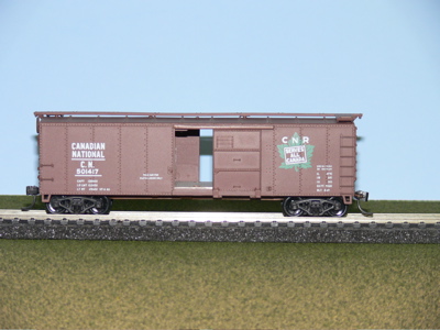
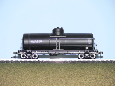
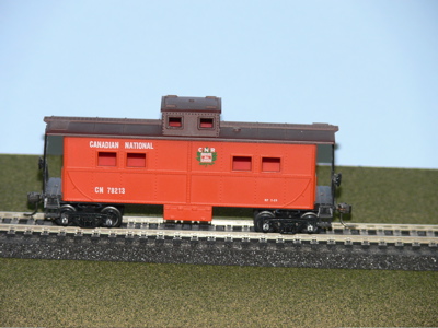
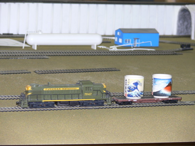
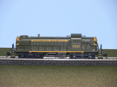
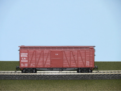
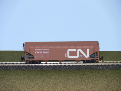
Now for a little fun. Here are images of my first four cars to be operational on the layout:
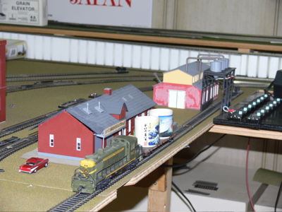
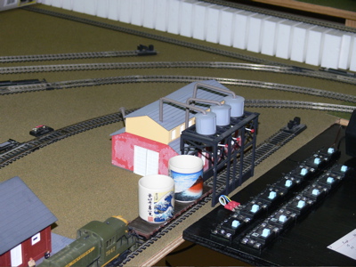
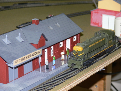
Here is my first operational load. CN diesel locomotive 7847 picked up the containers where the Lower Mainline Reversing loop passes by Distillery Row. They were taken to Happy Valley and unloaded at the 36th St Warehouse & Storage facility. Efforts were made to unload at the nearby flour mill but the containers were a touch oversize.
The inaugural trip is over and it is time for the engineer to file his report and then celebrate.
Overall this has been a great day. I think I will enjoy retirement.
My dominant philosophy is, and always has been, one of feedback and successive approximation. Thus I am looking forward to operating trains on the layout and making (hopefully minor) adjustments based on experience. The first change is a name change. Happy Valley will now be known as Paradise Valley. I wanted something like "Valley" to describe the fact that the town was on the lower level of the train layout. Happy did capture the fact that this entire activity is indeed a lot of fun, but Paradise is even better as it encompasses that idea plus it is a play on an extensive hiking trail in Banff that I took in 1966 which began at Lake Louise and then went to the summit of Mt. Fairview, then down to Paradise Valley and over Sentinal Pass to Larch Valley and finally down to Moraine Lake.
Distillery Row is perfect, and will not change. I like the allusion to Cannery Row.
Noon: This morning has been a relaxing time. I have conducted maintenance of 3 more cars. Each car was dusted off, the wheel sets checked for NRMA standard and the couplers checked for height and operation. I also took a photo of CN 7847, the diesel locomotive that is currently operating on the layout. These photos are also being included in the data base that I have for all my rolling stock.
I am continuing to work on assembling the wooden trestle bridge.
I am avoiding doing any operational running today, focusing instead on the regular maintenance of a few cars as I remove them from storage. I am also updating the data base for these cars. The data base program (FileMaker Pro 7.0) now has the capability of handling photos as a data type. I am delighted with this feature as I now can easily see which car corresponds to each record.
The first few cars were from the 1950's era, but I also have many cars from the 1970's with the CN 'noodle' logo (see hopper car, above). I plan my layout to have a combination of both eras existing simultaneously, with a few cars and locomotives from the 1990's also in appearance. This is another advantage of simulations: one can decide what to include and what to exclude. I like the early diesel units in the green and gold colors, the later units in the green, yellow and black colors and the modern units in the red, white and black colors.
7:45 PM Another good day. I began the morning with the idea of completing the Wooden Trestle kit but this quickly expanded to include the idea of building the necessary table structure to incorporate it into the layout.
Here are a couple of images of the result:
All tthat remains is to paint the three water barrels red. The barrels are intended to provide some form of fire suppression but I have some difficulty believing that a barrel of water would be of much help. I also have some difficulty believing that the structure could catch fire as the beams are all some distance apart. (This would make a great computer simulation!). The trestle has been given a coat of Dullcoat and it now looks much more realistic.
The Upper mainline loop is now ready for the final adjustments to make it operational. I am surprised at how quickly this has happened. I need to slow down a bit and focus on the lower level until it is closer to completion. I want to operationalize the Upper Mainline loop before I commit to buying the DCC controls. The actual scenery can be created later. Note in the last photo that the track has been laid for the first half of the trestle (it begins on the curve in the upper right hand corner of the photo). The lower level is in the upper left corner of the image, and the track on the white supports is the link joining the lower and upper levels.
I spent about an hour finalizing the actual assembly and another 3 hours working on the underlying table. I actually have two solutions: the immediate solution that allows me to work on the Upper Mainline loop and another table structure that I will incorporate in a few months time when I make a final decision to commit to building the extension to the upper level.
The remaining major project is to work on the oil refinery diorama.
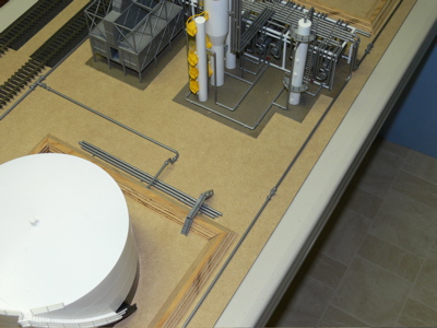
8:50 PM I put in a solid couple of hours laying the piping for the oil refinery diorama. The time was evenly spent between deciding where to put the pipes and actually cutting and glueing all of the pieces onto the layout. That part is now finished. I still have to add a ground cover (soil for the tank berms and ground near the tanks, grass for the rest of the layout).
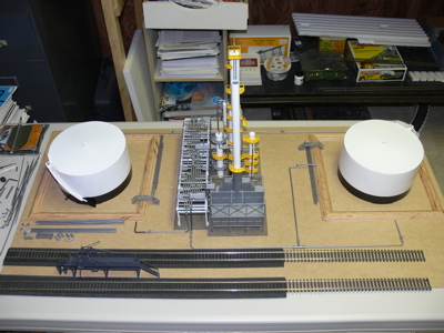
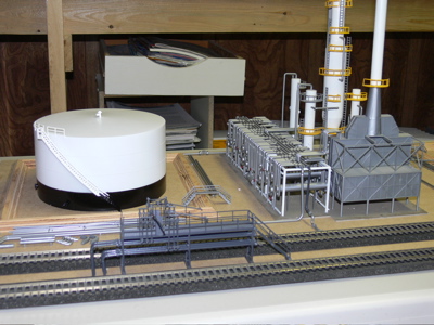
Here are a few images of the progress so far:
I am looking forward to adding the ground cover as this will be another new experience for me. Once I gain some confidence doing this, I will feel that I am in control as I work on the upper level where I have a coal mine and a lumber mill as well as the wooden trestle that all need some scenery additions.