 |
|
||||||||||||||
| Links to Notebook Pages: | Technology |
Model Trains |
Literature |
Wednesday July 12, 2006 5:00 am Lethbridge Alberta
A. Morning Musings
5:00 am This is better. I am up at 5 and feeling sharp and alert. The primary item for today is to take the 5th wheel in for a check up and new tires. It has been two months since we arrived home from Oz and we are finally getting the unit ready for use. The final step will be to actually set up in a campground.
The temperature is currently 14 C with a high forecast of 28 C. There is a 30% chance of showers or thunderstorms early this afternoon. That gives me an good excuse to postpone doing the parging around the rear step.
Instead I will spend some time working on my model train layout. The next item is to prepare a couple of diagrams for the two mainline track plans (upper & lower levels). If I can figure out a few of the commands for EazyDraw I should be able to create a diagram that I can print and then place under a clear pane of plastic to provide a map for the control panel. I will also be able to place the diagram on this web page.
B. Plan
Immediate Chores Take 5th wheel in for maintenance 2 hr Health Walk & exercise 1 hr Technology Make notes for chap. 2 of "Switching to the Mac" 1 hr Model Trains Use EazyDraw software to draw lower level mainline track layout 2 hr Literature Begin reading "Grizzly Lies" 1 hr Later Chores Take cement blocks to landfill 2 hr test saw blade for cutting 3/4" plywood (for book boxes project) 1 hr Investigate water softeners for home 2 hr Parge area around rear step to garage 1 hr Build 4 more book boxes Technology Read manual for cell phone 1 hr digital photography try using extender lens and monopod 2 hr Mathematics Larson "Calculus" Read "The Computational Beauty of Nature" Chap 2 1 hr Gardner "The Colossal Book of Short Puzzles" History Continue reading "Citizens" Watson "Ideas" Model Trains Add blue backdrop to layout 2 hr Review layout for under the table turnouts Purchase an NRMA gauge and some terminal blocks while in Edmonton Wire lower mainline track for a power block Fasten lower mainline track to layout
C. Actual/Notes
5:30 am
I read and yellow highlighted Chapter 2 Windows and Icons of "Switching to the Mac" a few days ago. Now it is time to make a few notes.
Chap. 2 Windows and Icons [p. 35 - 80]
- "While in the Finder menu the View -> Show View Options sequence provides a few additional options. One that is of interest is the Show Item Info which then adds a second line to the icon for any file that gives the number of items within a folder (if the icon is a folder) or the size of the file (if the item is a file)" [p. 40]
This is a new feature. I will try it for awhile and see if I prefer this additional information or if I find it clutters up the screen.
- "Click a 'flippy triangle' to see the listing of the folders and files inside that folder" [p. 45]
- "Mac OS X has a built in Web server - software that turns your Mac into an Internet Web site that people all over the world can connect to. ... This feature relies on a program called the Apache Web server. " [p. 53]
I was aware of this feature from conversations with Allan, but I have yet to try this out.
- "the spring-loaded folders feature ... Drag the icon onto the first folder - but keep your mouse button pressed. After a few seconds, the folder window opens automatically, centered on your cursor. Still keeping the button down, drag onto the inner folder so tht its window opens too. Now drag onto the inner inner folder, and so on." [p. 57]
- An alternative to dragging a file to the trash is to highlight the icon and then press command-delete. [p. 61]
- "See the little magnifying glass icon in your menu bar? That's the mouse-driven way to open the Spotlight search box. The other way is to press command-space bar. If you can memorize only one keystroke on your mac, that's the one to learn. ... As you type, a menu immediately appears below the search box, listing everything Spotlight can find containing what youve typed so far. [p. 65]
This is really cool!
- The Find... command ( under Finder ->File ) has some very interesting options. For example one can find all the files accessed in the last week. One can then save this result as a Smart folder. The contents of this folder are automatically updated and may be accessed at any time. [p. 80]
This is also really cool! These last two features are one's that are definitely worth forming a habit for.
Now to begin reading Chapter 3 The Dock, Desktop, Toolbar, and Sidebar.
6:55 am
9:30 am The 5th wheel is at the dealer's. We had no difficulty hooking it up and the drive over was uneventful (the tires held up). They will try to have it ready for me to pick up by Friday.
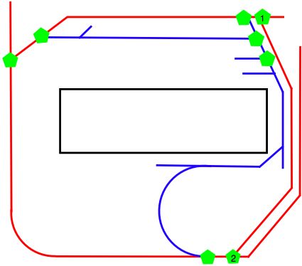
2:45 PM PM I have been playing with the EazyDraw software and it looks like it will meet my needs. It was very easy to save a copy of the file as a JPEG file and insert it into this web page. Here is a partially completed diagram of the Lower Mainline track structure:

The reason the diagram is incomplete is that the preview copy has a restriction on the number of elements that one can include in one file. The overall white area represents the table top area for the layout, which will consist of track and adjacent buildings and scenery. The red line indicates the mainline track circuit. The vertical line on the left side is the track that connects to the Upper Mainline layout. The blue line indicates a 'reversing loop' which is also part of the mainline track circuit. The green pentagons indicate turnouts (i.e. switches). The only turnouts on this diagram are those on the mainline (there are 11 altogether, with 4 presently unmarked on the diagram). The short track sections that join up to the mainline may represent a complex set of siding tracks and these will have their own control diagram and panel. The black rectangle in the center is an area that one may walk around in. I also want to add some additional labels indicating the nature of the some of the white sub-areas.
I plan to attach this diagram (when it is completed) beside a power pack (initially a variable DC current, but later a DCC current) and a set of turnout controls. I will use Atlas turnout controls since they came with the turnouts. Each turnout control (11 in all) will have 3 wires connecting the control to the actual turnout. This wiring will remain the same whether I use DC or DCC. This control panel will be placed in the top right corner of the walking area (i.e. black rectangle).
I have placed 3 terminal track sections (these are special pieces of track that have connecting screws for attaching the wire carrying the current to the track) on the layout, one near the control panel on the red section and one on the opposite side of the layout (near turnout #4 if you keep counting the green shapes beginning with 1, 2 and so on. The third terminal track is on the reversing loop section (blue line) near the control panel. I will mark these on the diagram later as well. A terminal strip with 8 connecting screws should (if I understand how these terminal strips work) allow me to have two wires from the power pack attach to two connecting screws and a pair of wires from each of the remaining 6 connecting screws will go to the 3 terminal track pieces. One should get a sense of how important it is to plan for the wiring before actual beginning to do it. Much to my surprise, I have one of these terminal strips with 8 connecting screws so I will be able to test this out.
The next step will be to tack down the lower mainline track and verify that I can run a locomotive on it. This will proceed in two phases. The first phase will be verify that the red circuit works and that a locomotive will run successfully on it. The second phase will be to tack down the track for the 'reversing loop' (blue line) and verify that this also will run a locomotive. There is some special considerations when wiring the blue section to ensure that one doesn't end up with a short circuit but I think I understand how this works and do not foresee any difficulties. Then I will begin wiring the turnouts and verifying that the overall system works as I envisage it.
At this point I will have two equally valid choices for my next step:
- repeat this process for the Upper Mainline circuit
- complete laying track and turnouts for some of the switching areas on the Lower level.
Then, and not before I can consider rewiring the mainline for DCC. However there is no point doing this until I have a DCC ready locomotive!
Once again, I have a real feeling of progress. I seem to know what I am doing and have the sequencing under control. However each actual step needs to be taken slowly and very carefully. I now need to pay particular attention to the laying of the track and ensuring that each individual piece is very carefully placed and mounted.
3:40 PM
6:30 PM I have just tried connecting two wires from the power transformer to the terminal strip and then two more wires from the terminal strip to a terminal track section. Nothing. I then tried a few combinations of hookup and discovered that the terminal does not work the way I thought. Each terminal is insulated from the other terminals. It makes sense when I think about it, but that means that there is no point in using it as I will need to connect the wires to each terminal post.
D. Reflection